Difference between revisions of "BlueprintGeometricAndTechDrawing"
Heltonbiker (talk | contribs) |
Romain2Boss (talk | contribs) m (Broken layout) |
||
| (One intermediate revision by one other user not shown) | |||
| Line 9: | Line 9: | ||
To perform a geometric construction (e.g., create a circle through 3 points), the corresponding "module" is activated in the toolbar, either by clicking on its icon or via a shortcut. Then the items on which this construction relies (i.e., the three points) are clicked. This creates the desired geometric object (in this case a circle passing through the points). | To perform a geometric construction (e.g., create a circle through 3 points), the corresponding "module" is activated in the toolbar, either by clicking on its icon or via a shortcut. Then the items on which this construction relies (i.e., the three points) are clicked. This creates the desired geometric object (in this case a circle passing through the points). | ||
[[Image:td_typical_workflow.png | [[Image:td_typical_workflow.png]] | ||
| Line 18: | Line 18: | ||
Some constructions that should be possible with the new tool: | Some constructions that should be possible with the new tool: | ||
[[Image:td_constructions.png | [[Image:td_constructions.png]] | ||
=== More advanced or less important === | === More advanced or less important === | ||
* "Preserve angles" mode for node editing of polygons (mockup courtesy of Johan Engelen) [[Image:td_preserve_angles_mode.png | * "Preserve angles" mode for node editing of polygons (mockup courtesy of Johan Engelen) | ||
[[Image:td_preserve_angles_mode.png]] | |||
* Marker improvements: | * Marker improvements: | ||
** Apply the color of the current stroke to markers, too (long-standing bug: LP #165865) | ** Apply the color of the current stroke to markers, too (long-standing bug: LP #165865) | ||
** The left image shows how a marker currently looks like when applied to a curve with a sharp turn. Of course, it should look like the one on the right (also note the above-mentioned bug that the marker doesn't take the curve's stroke color). [[Image:td_marker.png | ** The left image shows how a marker currently looks like when applied to a curve with a sharp turn. Of course, it should look like the one on the right (also note the above-mentioned bug that the marker doesn't take the curve's stroke color). | ||
[[Image:td_marker.png]] | |||
** Automatic path shortening when a marker is applied | ** Automatic path shortening when a marker is applied | ||
** Smarter way of guessing a suitable marker size (not only based on stroke width but maybe also on the length of the path) | ** Smarter way of guessing a suitable marker size (not only based on stroke width but maybe also on the length of the path) | ||
** Optional "bendy" markers that follow the curvature of the corresponding curve (see bug/wish [https://bugs.launchpad.net/inkscape/+bug/244279 #244279] for an example) | ** Optional "bendy" markers that follow the curvature of the corresponding curve (see bug/wish [https://bugs.launchpad.net/inkscape/+bug/244279 #244279] for an example) | ||
* Tangent snapping: [[Image:td_tangent_snapping.png | * Tangent snapping: | ||
[[Image:td_tangent_snapping.png]] | |||
| Line 51: | Line 58: | ||
Here is an example of part dimensioning: | Here is an example of part dimensioning: | ||
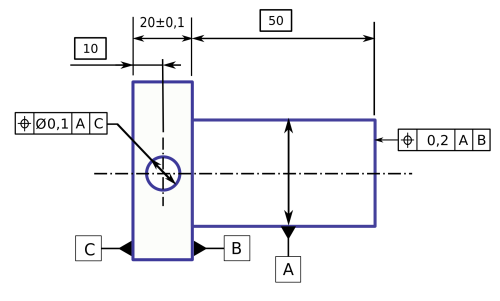
[[Image:Cotation_geometrique.png | [[Image:Cotation_geometrique.png]] | ||
=== Parametric Hatching === | === Parametric Hatching === | ||
| Line 71: | Line 78: | ||
As part of the project, it is intended to integrate LPEs much more tightly into Inkscape's UI, e.g., by providing handles for parameter adaption or making their controls available in toolbars (not only in the LPE dialog). | As part of the project, it is intended to integrate LPEs much more tightly into Inkscape's UI, e.g., by providing handles for parameter adaption or making their controls available in toolbars (not only in the LPE dialog). | ||
[[Category:Proposals]] | |||
Latest revision as of 13:21, 30 March 2012
Summary
This blueprint accompanies the GSoC'08 project "Geometric & Tech Drawing Abilities for Inkscape" by Maximilian Albert. It collects ideas from the community regarding desired features and their implementation (with no warranty that any of them will be included in the project :)). Feel free to add your thoughts here.
The aim of the project is to create a new tool consisting of a number of "subtools"/"modules" which facilitate geometric constructions and technical drawings.
Typical Workflow
To perform a geometric construction (e.g., create a circle through 3 points), the corresponding "module" is activated in the toolbar, either by clicking on its icon or via a shortcut. Then the items on which this construction relies (i.e., the three points) are clicked. This creates the desired geometric object (in this case a circle passing through the points).
Desired Constructions/Other Features
Basic
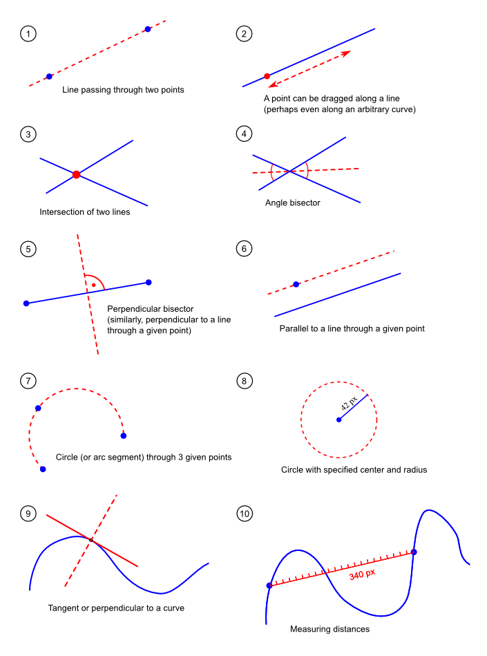
Some constructions that should be possible with the new tool:
More advanced or less important
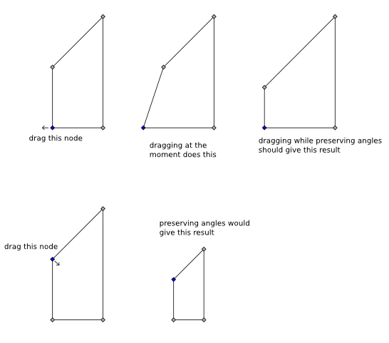
- "Preserve angles" mode for node editing of polygons (mockup courtesy of Johan Engelen)
- Marker improvements:
- Apply the color of the current stroke to markers, too (long-standing bug: LP #165865)
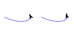
- The left image shows how a marker currently looks like when applied to a curve with a sharp turn. Of course, it should look like the one on the right (also note the above-mentioned bug that the marker doesn't take the curve's stroke color).
- Automatic path shortening when a marker is applied
- Smarter way of guessing a suitable marker size (not only based on stroke width but maybe also on the length of the path)
- Optional "bendy" markers that follow the curvature of the corresponding curve (see bug/wish #244279 for an example)
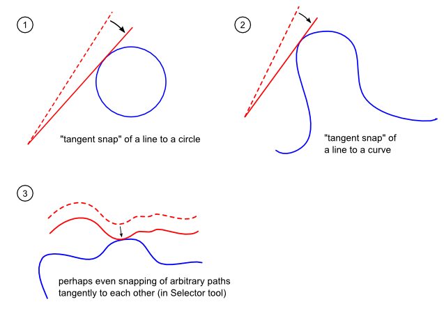
- Tangent snapping:
Geometric dimensioning and tolerancing abilities
The tool will need all the dimensioning abilities a normal CAD software has in respect of the ISO Geometric dimensioning and tolerancing specifications.
- Linear dimensions (with arrows pointing outwards <-----> for big dimensions and inwards ->--<----- for small dimensions
- Radius/Diameter and Angle dimensions;
- Horizontal/Vertical/Aligned dimensions;
- On every dimension there should be the possibility of adding a text box and overriding the default dimension value,...
- Possibility to modify the drawing by editing its dimensions, the same way is done in Parametric Sketching programs (e.g. Inventor, SolidWorks,...)
Here is an example of part dimensioning:
Parametric Hatching
Current pattern fill is by far to complicate for technical drawings. A parametric hatching like proposed here [1] or here [2] would be a great simplification.
Most hatches are created from one, two or three sets of parallel lines that have individual distances, angles, widths and line styles. So a parametric hatch definition could create this by an arbitrary amount of hatch layers with each having one parallel set of lines. The number of layers does not have to be restricted in the user interface, but for simplification three layers are enough.
A set of hatch parameters should be storable with a name to reuse it. Changing the parameters of a stored set should have a global effect and affect all objects using it.
Details & Internals
User Interface
All constructions should be accomplishable by mouse input only. E.g., points can be specified by mouse clicks, their position can be adapted by dragging, as can angles of lines, radii of circles, etc. But since for technical drawings the ability to use exact values is indispensable, each of these values can also be set by using numeric input fields (e.g., in the secondary toolbar).
Code
The tool will be implemented as a collection of "Live Path Effects" (LPEs). See here for a technical description. The algorithms will be provided by the 2geom library which is intended to become Inkscape's core library in the near future. There are separate GSoC proposals for 2geom integration into Inkscape.
As part of the project, it is intended to integrate LPEs much more tightly into Inkscape's UI, e.g., by providing handles for parameter adaption or making their controls available in toolbars (not only in the LPE dialog).

