Difference between revisions of "PowerStroke"
Johanengelen (talk | contribs) |
m |
||
| (4 intermediate revisions by 2 users not shown) | |||
| Line 1: | Line 1: | ||
= LGM 2012 Presentation = | = LGM 2012 Presentation = | ||
A PDF of | A PDF of Johan's presentation at LGM 2012 in Vienna: [[File:LGM2012 - Powerstroke.pdf]] | ||
SVG source files: ''should be linked here soon...'' | SVG source files: ''should be linked here soon...'' | ||
| Line 34: | Line 34: | ||
A combination of a metakey and the scroll wheel would be intuitive as well (with status bar message stating you can do that, of course). -- [[jegHegy]] | A combination of a metakey and the scroll wheel would be intuitive as well (with status bar message stating you can do that, of course). -- [[jegHegy]] | ||
As of inkscape-1.0.1 the implementation is different than what is described here. | |||
* When added, the Path Effect PowerStroke produces 3 additional pink handles that can be dragged around intuitively: | |||
** A pink handle can be moved along the length of the path to define where it should have its effect. | |||
** A pink handle can be dragged away from or closer to the center of the path to make the stroke at this position thicker or thinner. | |||
* To add another pink handle, you can duplicate one of the existing ones with '''CTRL-Click''', and then drag it away along the path. | |||
* To remove a pink handle, '''CTRL-ALT-Click''' on it. | |||
* To position a pink handle at exact coordinates, '''Shift+Click''' or '''ALT-Click''' on it, an entry box opens. | |||
-- [[User:Jnweiger|Jnweiger]] ([[User talk:Jnweiger|talk]]) | |||
= Comments = | = Comments = | ||
Latest revision as of 01:29, 25 January 2021
LGM 2012 Presentation
A PDF of Johan's presentation at LGM 2012 in Vienna: File:LGM2012 - Powerstroke.pdf
SVG source files: should be linked here soon...
Power stroke
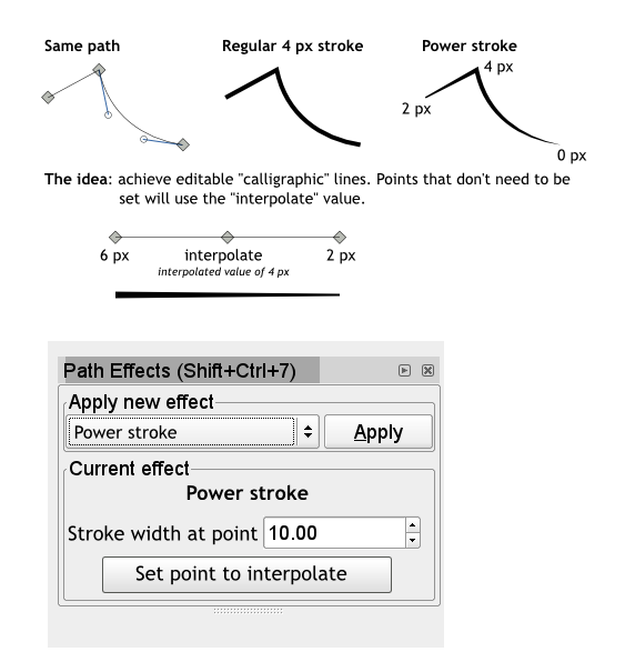
The proposed power stroke LPE is as follow:
Functionality
This LPE allows a modulated stroke from manually entered values.
Further development could allow direct width reading from a pressure-enabled device.
Workflow
The user simply creates the line, it might for example be based on an outline.
Then the user applies the LPE to his shape, it overrides the normal stroke rendering and allows custom line width at different nodes of the path.
Only the stroke-width property of the path is overridden, the rest of the stroke properties keep working as usual, when relevant.
GUI
Se image above. User selects a nodes or a set of nodes and affects values to those. When a node is selected, you can see what its value is by the change in values in the number entry or by the state of the push button.
Additionally, hovering over a node could show the value of a node. Graphical feedback could even possibly set different icons for nodes that are set and others that are interpolated.
Perhaps Alt+drag a node to change the thickness?
A combination of a metakey and the scroll wheel would be intuitive as well (with status bar message stating you can do that, of course). -- jegHegy
As of inkscape-1.0.1 the implementation is different than what is described here.
- When added, the Path Effect PowerStroke produces 3 additional pink handles that can be dragged around intuitively:
- A pink handle can be moved along the length of the path to define where it should have its effect.
- A pink handle can be dragged away from or closer to the center of the path to make the stroke at this position thicker or thinner.
- To add another pink handle, you can duplicate one of the existing ones with CTRL-Click, and then drag it away along the path.
- To remove a pink handle, CTRL-ALT-Click on it.
- To position a pink handle at exact coordinates, Shift+Click or ALT-Click on it, an entry box opens.
Comments
By JohanE
This is very well doable, but would require a new "Nodepath" implementation that enables writing special values (preferably a struct) per node. There is already something like this, the "nodetypes" attribute, but it is too restrictive. Expanding this would enable this effect, and opens up many other possibilities. Nice idea !
By Pajarico
I'm thinking this tool could allow the user to copy a path or an object or group of objects to any node in a path. Which is similar to what you're proposing, only this doesn't use interpolation between adjacent nodes, it just places an element on a specific node (or nodes if you have several selected).
I'm not sure if it is better to open a separate blueprint or not. --Pajarico, Pajarico 22:36, 21 June 2008 (UTC)
By rubikcube
You might want to have a look at how synfig handles varying width for paths. Paths are called "Blines" there, the relevant feature is explained shortly at the bottom of one of its manual pages. --Rubikcube 17:26, 3 September 2008 (UTC)
By Klesus
In concept I've been thinking of this for a long time, so I'm hopeful that this possibly could be expanded to allow control of other things than stroke width like say, stroke color, opacity and perhaps even blur(!) although I doubt blur is something that would be impossible to implement. Just my 2 cents.
By dvlierop
Can this be coupled to the pressure applied using a tablet, while drawing a line? I think this would allow to create an LPE powerstroke in the most possible intuitive way. But I'm more a CAD guy than an artist, so I might be totally off.
Discussion at LGM 2010
We had a nice discussion about Power Stroke at LGM2010. Here follows some of the 'results' of the discussion and sketches...
 - effect should be intuitive and simple. advanced features
   that are difficult to control should be implemented in
   another "advanced power stroke" effect if desired
 - how to change the stroke width of multiple control points at the same time?
 - width is controllable at original path's knots
 - the type of width interpolation between knots should depend
   on original path's knot type (smooth, cusp, etc.)
 - provide options for end caps
 - offer possibility of asymmetric control points
 - width control handles should be perpendicular to the original path
 - keep it simple and useable! don't provide the one effect to rule them all.
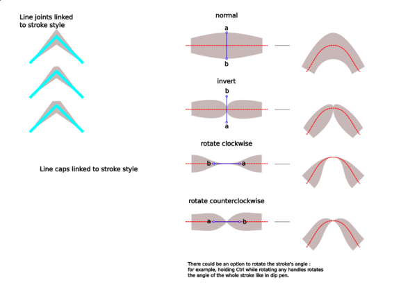
An interesting sketch by Ivan Louette:
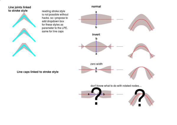
I have several questions about this drawing: shouldn't the edge of the stroked path always pass through the stroke width control nodes? The inverted one for example, shouldn't the stroke be 'inverted' and have the width a-b? (so the zero width stroke should happen on the left and right of the control knot?)
I propose the following:
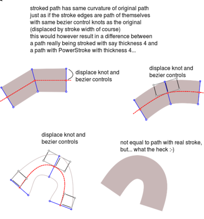
with implementation:
Johan Engelen's implementation (0.48+dev) as LPE
Since the GSoC project was stopped, Johan has begun to implement the powerstroke lpe. To test the LPE, Inkscape must be built with experimental LPE's enabled. You have to build Inkscape with
#define LPE_ENABLE_TEST_EFFECTS
otherwise the LPE won't show in the LPE dialog. (uncommenting line 9 in src/live_effects/effect.cpp will do the trick)


