Advanced Gradients
There are (apparently) several types of gradients that can be interesting to support, but are not part of the SVG standard. This page is meant to document which gradient types Inkscape may want to support and how these could be simulated.
This page was started as part of the response to bug 346681, mainly to provide an alternative for a bitmap fallback.
Separating shape/pattern from color
Any gradient can be defined by a mapping [math]\displaystyle{ f }[/math] from any point in the plane to a value in the range [math]\displaystyle{ [0,1] }[/math], combined with a mapping from the range [math]\displaystyle{ [0,1] }[/math] to colors. The former is defined by the type of gradient (and its parameters) and the latter by the gradient stops.
For each new gradient type it suffices to find a good method of generating [math]\displaystyle{ f }[/math] (over all four color channels). The desired colors can then be determined by using an feComponentTransfer filter with the table transfer function type. This allows the gradient to be approximated to any required accuracy. An example for a gradient from red to green to blue to transparent black (assumes we are in a filter definition and an image with [math]\displaystyle{ f }[/math] on all four channels is in "f"):
<feComponentTransfer in="f">
  <feFuncR type="table" tableValues="1 0 0 0" />
  <feFuncG type="table" tableValues="0 1 0 0" />
  <feFuncB type="table" tableValues="0 0 1 0" />
  <feFuncA type="table" tableValues="1 1 1 0" />
</feComponentTransfer>
The two images below show an example as it is rendered by Inkscape and Batik. As can be seen the quality of the gradient is degraded in the top area, where the alpha values are low, likely due to the use of premultiplied alpha. It should be possible to fix this by separating [math]\displaystyle{ f }[/math] into an opaque color component and an alpha-only component, applying the component transfer tables separately and then combining them again.
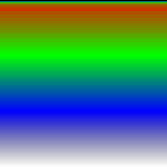
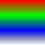 Download/view LineargradientCT.svg
Alternatively the mapping to colors of the gradient could be done using feDisplacementMap, if [math]\displaystyle{ f }[/math] is pre-processed properly. Specifically, the values of [math]\displaystyle{ f }[/math] are meant to be interpreted in an absolute sense, while feDisplacementMap uses them as an offset relative to the current position. So if [math]\displaystyle{ (x1,y1),(x2,y2) }[/math] defines the bounding box of the object to which the gradient is applied, and a (horizontal) linear gradient is applied to a rectangle using these same coordinates, then the scale parameter should be set in such a way that [math]\displaystyle{ x1+scale*0.5=x2 }[/math] and [math]\displaystyle{ x2-scale*0.5=x1 }[/math], so [math]\displaystyle{ scale=2(x2-x1) }[/math]. The x displacement channel should then be set to a channel corresponding to the pre-processed [math]\displaystyle{ f }[/math] and the y displacement channel should then be set to some channel that is 0.5 everywhere. An example for the same gradient as above (we are in a defs element, the red channel is assumed to correspond to [math]\displaystyle{ f }[/math] and the green channel to one, the bounding box is assumed to be [math]\displaystyle{ (0,0),(1,1) }[/math]):
<g id="symbolstops">
  <linearGradient id="gradientstops">
    <stop offset="0" stop-color="#f00" />
    <stop offset="0.33" stop-color="#0f0" />
    <stop offset="0.67" stop-color="#00f" />
    <stop offset="1" stop-color="#000" stop-opacity="0" />
  </linearGradient>
  <rect width="150" height="150" fill="url(#gradientstops)" />
</g>
<g id="symbolxoffset">
  <linearGradient id="gradientxoffset">
    <stop offset="0" stop-color="#F00" />
    <stop offset="1" stop-color="#000" />
  </linearGradient>
  <rect width="1" height="1" fill="url(#gradientxoffset)" />
</g>
<filter ...>
  ...
  <feImage xlink:href="#symbolxoffset" result="xoffset" />
  <feComposite in="f" in2="xoffset" result="fp" operator="arithmetic" k2="0.5" k3="0.5" />
  <feImage xlink:href="#symbolstops" result="stops" />
  <feDisplacementMap in="stops" in2="fp" scale="2" xChannelSelector="R" yChannelSelector="G" />
</filter>
This last method has the advantage that there is a more direct correspondence with the gradient stops defined by the user (and does not use an approximation to the gradient as the feComponentTransfer method), but it is obviously also more complex. Also, if the mapping [math]\displaystyle{ f }[/math] needs a (non-linear) correction this can directly be taken into account in the feComponentTransfer method. However, the feComponentTransfer method can give a lower quality result if the alpha channel is also part of the gradient (and the viewer uses premultiplied alpha).
The images below show a linear gradient colored with the feDisplacementMap method, rendered by the Inkscape and Batik. Clearly this method alleviates the problems with using premultiplied alpha that the feComponentTransfer method has. However, to avoid sampling just outside the defined area the linear gradient has been scaled a bit, and with it [math]\displaystyle{ f }[/math] (as this is more precise than scaling [math]\displaystyle{ f }[/math] afterwards).
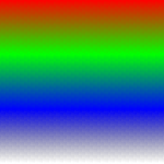
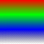 Download/view LineargradientDM.svg
Conical gradient
"A gradient which goes along the circular arc around a center." In other words (ignoring rotations and so on), given a center [math]\displaystyle{ (cx,cy) }[/math], the mapping [math]\displaystyle{ f }[/math] is defined as:
[math]\displaystyle{ f(x,y)=\frac{1}{2\pi}\arctan(y-cy,x-cx)+\frac{1}{2} }[/math]
One way to mimic a conical gradient is to use a circular gradient to define a conical surface and then use feDiffuseLighting with surfaceScale set to half the radius of the gradient and a distant light source with an elevation of 45 degrees. This doesn't directly result in the right mapping, but it at least shares the property that the pixels on radial lines from the center have the same value. In addition, the generated gradient will be symmetrical, so if this is not wanted the region should be split in two along the symmetry axis.
Another (arguably simpler) way to achieve the exact same effect would be to again use a radial gradient and approximate a directional derivative using a convolution. The offset should now be 0.5 (0 is the "middle" value) and the divisor should be [math]\displaystyle{ 2/r }[/math], assuming the matrix is already properly scaled to truely approximate the gradient.
The following images show the feDiffuseLighting method (as Batik does not support feConvolveMatrix with a bias) used with the feDisplacementMap as the result appears in Inkscape and Batik:
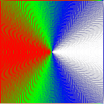
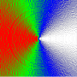 Download/view ConicalgradientDMDL.svg
Another method that works both with Inkscape and Batik is to simply compute the cosine directly. This can be done by creating a linear gradient corresponding to the x-coordinate and a radial gradient corresponding to the distance to the center, then computing the reciprocal of the distance function (using feComponentTransfer) and finally multiplying this by the x-coordinate (using appropriate scaling and offset) with feComposite. This has the advantage that no resolution dependent filters are used, but the precision of the reciprocal is quite low in most (if not all) renderers. Luckily this can, to a great extent, be solved using iterative refinement, resulting in the following images:
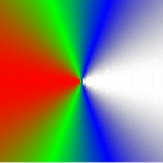
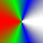 Download/view ConicalgradientDMRD.svg
Using the method of multiplying by reciprocal distance we can also define a (much) better approximation to a true conical gradient by dividing by the [math]\displaystyle{ l_1 }[/math] (Manhattan) distance to the center ([math]\displaystyle{ |x|+|y| }[/math]) instead of the [math]\displaystyle{ l_2 }[/math] (Euclidean) distance. This results in the following (note that this SVG uses the alpha component for computations and apparently Batik has some problems with this):
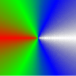
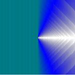 Download/view ConicalgradientDMRD2.svg
Arctan approximation quality
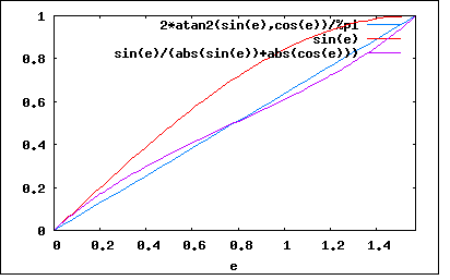
The following graph shows the difference between approximating the angle by [math]\displaystyle{ x }[/math] divided by the [math]\displaystyle{ l_2 }[/math] distance to the center (the cosine) or [math]\displaystyle{ x }[/math] divided by the [math]\displaystyle{ l_1 }[/math] distance to the center (note that in this graph the roles of x and y are reversed, as this corresponds better to how angles are normally defined):
Note that this approximation method corresponds to the approximation described here for quadrant 1 (with the roles of x and y reversed, just like in the graph above), scaled by [math]\displaystyle{ 2/\pi }[/math]:
[math]\displaystyle{ \begin{align} \frac{2}{\pi}\cdot\frac{\pi}{4}\left(1-\frac{y-x}{x+y}\right)&=\frac{1}{2}\left(1-\frac{y-x}{x+y}\right) \\&=\frac{1}{2}\left(\frac{x+y}{x+y}+\frac{x-y}{x+y}\right) \\&=\frac{1}{2}\left(\frac{x+y+x-y}{x+y}\right) \\&=\frac{1}{2}\left(\frac{2x}{x+y}\right) \\&=\frac{x}{x+y} \end{align} }[/math]
Formal derivation of feDiffuseLighting method
To derive the right parameters, first define the (ideal) surface of the cone created by the gradient as (setting the center to [math]\displaystyle{ (0,0) }[/math] without loss of generality):
[math]\displaystyle{ Z(x,y)=s-\frac{s}{r}\sqrt{x^2+y^2} }[/math]
Per the SVG 1.1 specification the surface normal is defined by using a Sobel filter, however, as this is a reasonable approximation of a directional derivative we use the derivative instead. Specifically, taking the right scale factors into account, the surface normal is defined as:
[math]\displaystyle{ \begin{align} N'_x(x,y)&=-2 \frac{\partial}{\partial x}Z(x,y) \\&=\frac{2sx}{r\sqrt{x^2+y^2}} \\N'_y(x,y)&=\frac{2sy}{r\sqrt{x^2+y^2}} \\N'_z(x,y)&=1 \\N(x,y)&=\frac{N'}{\|N\|} \end{align} }[/math]
Assuming a distant (white) light source with a zero azimuth and a diffuse lighting constant of one, the intensity of the resulting image can now be computed as:
[math]\displaystyle{ \begin{align} D(x,y)&=N(x,y)\cdot L(e) \\&=\frac{1}{\|N'(x,y)\|}\left(\frac{2sx}{r\sqrt{x^2+y^2}}\cos(e)+\sin(e)\right) \\&=\frac{1}{\sqrt{4s^2+r^2}\sqrt{x^2+y^2}}\left(2sx\cos(e)+r\sqrt{x^2+y^2}\sin(e)\right) \end{align} }[/math]
To get a nice gradient we can now demand that [math]\displaystyle{ D(x,0) }[/math] is zero for negative [math]\displaystyle{ x }[/math] and one for positive [math]\displaystyle{ x }[/math] and solve for [math]\displaystyle{ s }[/math] and [math]\displaystyle{ e }[/math]:
[math]\displaystyle{ \begin{align} D(x,0)&=\frac{1}{\sqrt{4s^2+r^2}|x|}\left(2sx\cos(e)+r|x|\sin(e)\right) \\&=\frac{1}{\sqrt{4s^2+r^2}}\left(2s\mbox{sign}(x)\cos(e)+r\sin(e)\right) \\D(x_-,0)&=0 \\0&=\frac{1}{\sqrt{4s^2+r^2}}\left(-2s\cos(e)+r\sin(e)\right) \\2s\cos(e)&=r\sin(e) \\\frac{\sin(e)}{\cos{e}}&=\frac{2s}{r} \\e&=\arctan(\frac{2s}{r}) \\D(x_+,0)&=1 \\1&=\frac{1}{\sqrt{4s^2+r^2}}\left(2s\cos(e)+r\sin(e)\right) \\\sqrt{4s^2+r^2}&=2r\sin(e) \\\sqrt{4s^2+r^2}&=\frac{4rs}{r\sqrt{\frac{4s^2}{r^2}+1}} \\\sqrt{4s^2+r^2}&=\frac{4rs}{\sqrt{\frac{4s^2}+r^2}} \\4s^2+r^2&=4rs \\4s^2-4rs+r^2&=0 \\(2s-r)^2&=0 \\s&=\frac{1}{2}r \\e&=\arctan(1) \\&=\frac{1}{4}\pi \end{align} }[/math]
So surfaceScale should be half of the radius of the radial gradient and the elevation of the light source should be 45 degrees. By filling in this result in [math]\displaystyle{ D }[/math] it is apparent that the intensity now corresponds exactly to the cosine of the angle we are really interested in with a conical gradient (scaled and translated to fit in the range [math]\displaystyle{ [0,1] }[/math]):
[math]\displaystyle{ \begin{align} D(x,y)&=\frac{1}{\sqrt{4(\frac{1}{2}r)^2+r^2}\sqrt{x^2+y^2}}\left(2\frac{1}{2}rx\cos(\frac{1}{4}\pi)+r\sqrt{x^2+y^2}\sin(\frac{1}{4}\pi)\right) \\&=\frac{1}{\sqrt{2}\sqrt{x^2+y^2}}\left(x\frac{1}{\sqrt{2}}+\sqrt{x^2+y^2}\frac{1}{\sqrt{2}}\right) \\&=\frac{x}{2\sqrt{x^2+y^2}}+\frac{1}{2} \end{align} }[/math]
For a perfect result it should now be taken into account that we have a cosine and not an angle, but this may not always be an issue.
Spiral gradient
Here defined as similar to a conical gradient, but with the mapping [math]\displaystyle{ f }[/math] also depending on the distance to the center. Specifically:
[math]\displaystyle{ f(x,y)=\frac{1}{2\pi}\arctan(y-cy,x-cx)+\sqrt{(x-cx)^2+(y-cy)^2}\mod 1 }[/math]
If a conical gradient can be created then this can be created by simply adding the distance to the center. If needed use can be made of the fact that modular arithmetic is used (that is, a long steep gradient is equivalent to many small, equally steep, gradients).
To avoid overflow in the mapping it can be scaled by 0.5, allowing two "periods" in the [math]\displaystyle{ [0,1] }[/math] range. In this case the mapping to colors should be changed accordingly.
More
Diffusion curves? See [[1]], as well as this Wiki page for information on attempts to make Diffusion Curves suitable for implementation in Inkscape.
